
📐Introduction
In the intricate world of modern architectural facades, the unitized curtain wall system stands as the pinnacle of efficiency, aesthetics, and performance. For architects, general contractors, and developers, understanding the unitized curtain wall standard panel size range is not merely a matter of geometry; it is a critical economic and logistical calculation that can define the success or failure of a high-rise project.
The Golden Ratios of Fabrication
At APRO, having manufactured and installed millions of square meters of facades globally, we have learned that “standard” is a fluid concept. While customizability is a hallmark of unitized curtain walls, adhering to specific dimensional logic—what we call the “golden ratios” of fabrication and logistics—can save up to 30% in project costs and reduce installation time by weeks.
This comprehensive guide will move beyond basic definitions. We will dissect the unitized curtain wall panel standard width and height, explore the typical unitized curtain wall module size by floor height, and dive deep into the often-overlooked details like unitized curtain wall joint width and tolerance management. Whether you are designing a supertall tower in Dubai or a sprawling airport terminal in Shanghai, this guide is your blueprint for dimensional precision.
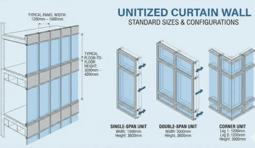
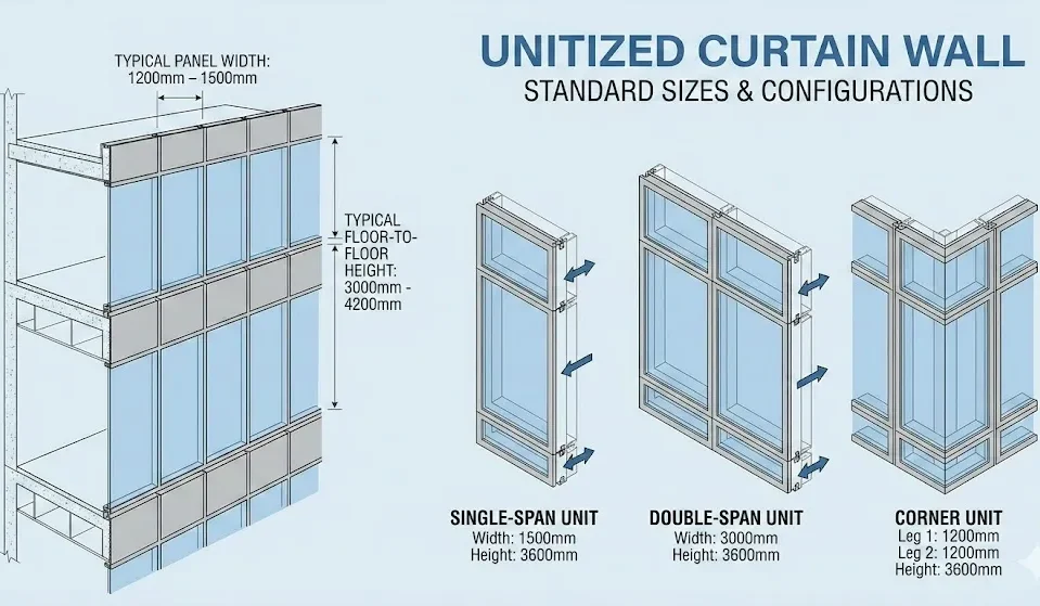
📏Unitized Curtain Wall Standard Panel Size Range
When clients ask, “what are the standard sizes of unitized curtain wall panels?”, the answer lies in the intersection of material limits, transport constraints, and aesthetic proportions. While we can fabricate almost anything, staying within specific ranges ensures optimal performance and cost-efficiency.
↔️ What is the Standard Width?
The unitized curtain wall panel standard width typically ranges between 1200mm and 1500mm (approx. 4 to 5 feet).

Why this range?
- Glass Yield: Standard float glass sheets (Jumbo size) are typically 3300mm or 3210mm wide. A 1500mm module allows efficient cutting with minimal waste.
- Office Planning: Most Grade-A office buildings utilize a planning grid of 1500mm to accommodate office partitioning.
- Handling: Widths >1800mm stress the hoisting weight limit and make manual manipulation dangerous.
↕️ What is the Standard Height?
Dictated almost exclusively by the floor-to-floor height of the building.

- Standard Range: 3500mm to 4200mm (approx. 11.5 to 14 feet).
- Split Strategy: The unitized curtain wall stack joint is usually located roughly 1000mm to 1200mm above the finished floor level (aligning with a sill/transom) for easy installer access.
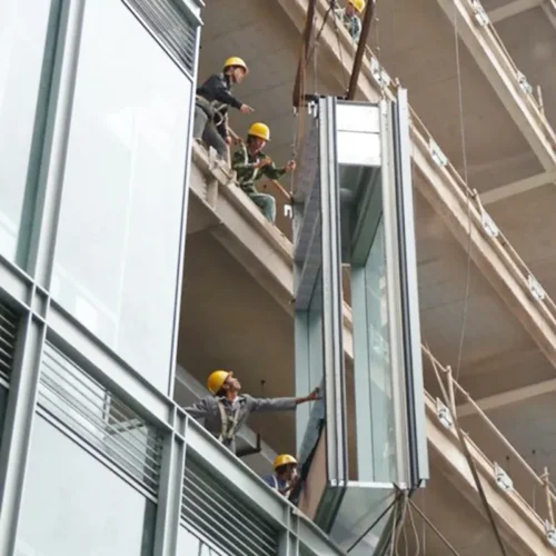
🏭 Factory Experience: Super-Height Panels
“I recall a luxury hotel project we managed in Southeast Asia where the lobby podium required unitized curtain wall panels spanning 7.5 meters high without intermediate slab support.”
Standard extrusion presses could not produce a single continuous mullion of that length with sufficient stiffness; standard shipping containers couldn’t fit 7.5m units.
We engineered a ‘splice-mullion’ technique. We fabricated the unit in two pieces (4m and 3.5m) with a steel insert sleeve. On-site, we set up a ‘flying factory’ to structurally join them before hoisting as a single mega-unit.
📐 What is the Typical Depth?
The depth is purely a function of structural mechanics (preventing excessive deflection).
- Low to Mid-Rise: 150mm to 180mm.
- High-Rise (High Wind Load): 200mm to 250mm.
- Typical High-Rise Frame: Often settles around 175mm to 225mm.
🔲 What is the Typical Glass Thickness?
- Standard Double Glazed Unit (DGU): 26mm – 32mm total (6mm Glass + Air Space + 6mm Glass).
- High-Performance Laminate: 34mm – 42mm (Includes laminated inner layer for safety/acoustics).
- Spandrel: Often 6mm single tempered or thinner DGU with opaque frit + insulation.
🔗 Standard “Joint Width/Stack Joint”
This dimension is critical; it is the “lungs” of the façade, accommodating thermal expansion, creep, and seismic drift.
- Vertical Joint (Split Mullion): Typically 10mm to 15mm.
- Horizontal Joint (Stack Joint): Typically 15mm to 25mm (up to 35mm in seismic zones).
🏗️What Factors Influence Curtain Wall Dimensions?
Determining how to choose module width for unitized curtain wall design involves balancing five competing forces.
1. Architecture and Facade Division (Grid, Bay, WWR)
The unitized curtain wall module size based on building grid is the starting point.

- Visual Alignment: Architects often want vertical mullions to align with interior partition walls. (e.g., An 8.4m grid divided by 6 = 1.4m module).
- Window-to-Wall Ratio: Energy codes often dictate glass vs. opaque spandrel ratios. This might force the vision glass height to be reduced, affecting transom placement.
2. Structural Conditions and Floor Height
Unitized curtain wall design around slab edge and beams is critical.

- Slab Edge: If the slab edge is uneven, the stack joint design must have enough tolerance to absorb the deviation.
- Corner Panels: Corners are usually “L” shaped and must be sized slightly smaller than standard units to allow for 3D maneuvering during installation.
3. Load and Displacement Requirements
This is where engineering dictates geometry.

- Wind Load: In coastal typhoon zones, higher pressures mean glass must be thicker, or panel size reduced to prevent bowing.
- Seismic Drift: If a floor moves 20mm during an earthquake, the stack and vertical joints must be able to open/close by that amount without frame/glass contact.
4. On-Site Installation and Logistics Constraints
Never design a panel you cannot ship.

- Shipping: Standard 40ft High Cube containers have a door height of ~2.58m. Panels wider than 3m require expensive Open Top containers or risky tilting.
- Hoisting: Tower cranes have weight limits at the jib tip. Heavy panels (e.g., 500kg) might be unliftable at the building’s far corners.
🏢 Real Case Study: The Eagle Mall
At The Eagle Mall project, we faced a significant logistical hurdle. The design called for extra-wide 2.4m panels to maximize shopfront visibility.
Dense urban site with strict road closure rules. Internal goods lift was too narrow for 2.4m crates; oversized trucks were banned during the day.
We proposed a “Split-Mullion Ladder” system. Frames were shipped knocked-down (KD) and glazed on the floor slab immediately prior to installation.
While this shifted some labor to the site, it solved the transport issue while maintaining unitized water management. The project opened on time without massive crane penalties.
5. Fabrication and Cost Factors
Cost optimization through standard module sizes is the secret weapon of budget control.

- Glass Yield: If design results in 40% glass waste from raw sheets, you pay for that waste.
- Molds: Minimizing unique die profiles reduces upfront tooling costs significantly (standardization vs custom panels cost analysis).
📏How to Measure and Plan Unitized Curtain Wall Sizes
Step 0 — Set the “Rules of the Game” (Before Any Measuring)
Goal: Decide what is fixed, what can move, and what counts as “acceptable deviation.”
- Collect contract documents (elevations, structural drawings, specs).
- Define control datums (Horizontal: finished floor? Vertical: gridlines?).
- Define responsibilities (Who surveys? Who owns embed coordination?).
- Agree on tolerance assumptions (slab edge, embed placement).
Step 1 — Gather “As-Built” Geometry (Don’t Trust IFC Alone)
Goal: Get real slab-edge and embed locations, not theoretical drawings.
- Slab edge line (in/out & elevation deviation).
- Embed plates / channels (location + edge distance).
- Beam drops / perimeter beams (clearance checks).
- Corner geometry (offsets, twists).
Step 2 — Build a Tolerance Budget (This Is the Core)
Goal: Convert messy site reality into numbers your unit/joint can survive. Create a table like this:
| Source of variation | Typical direction | Your project value | Notes |
|---|---|---|---|
| Concrete slab edge (in/out) | ± | __ mm | by survey |
| Concrete elevation (up/down) | ± | __ mm | by survey |
| Embed placement | ± | __ mm | by survey |
| Steel/concrete drift (floors) | ± | __ mm | structure |
| Fabrication tolerance | ± | __ mm | factory capability |
| Installation tolerance | ± | __ mm | crew + method |
| Thermal movement allowance | + / – | __ mm | calc/assumption |
| Interstory drift allowance | + / – | __ mm | structure |
- Maximum required adjustment at anchors (x/y/z)
- Minimum and maximum joint opening you must handle (vertical + stack joints)
Step 3 — Decide the Panelization Strategy
Goal: Make the façade “repeatable,” while controlling exceptions.
- Lock default height: 1-floor-high unit (recommended baseline).
- Identify non-typical: Podium, mechanical floors, lobbies.
- Split into zones: Zone A (Typical), Zone B (Podium), Zone C (Corners).
- Target module width: Align with grid, avoid too many variants.
Step 4 — Pick Preliminary Unit Width/Height
Goal: Choose dimensions that fit architecture + structure + logistics.
- Height: Floor-to-floor minus designed stack joint. Verify ceiling/sill conditions.
- Width: Match grid rhythm. Verify glass supplier limits.
- Weight Check: IGU weight ≈ 25 kg/m² per 10mm glass. Check crane radius.
Step 5 — Joint Width Sizing (Do This With Numbers)
Goal: Define joint sizes that can handle movement + tolerances and still seal.
- Define worst-case: Max/Min opening based on tolerance + drift + thermal.
- Check gasket: Must maintain wiping/compression across range.
- Confirm drainage: Ensure water path and pressure equalization.
Step 6 — Anchor/Bracket Adjustment Design
Goal: Ensure anchors can actually absorb the deviations you measured.
- Adjustment: Use tolerance budget to define required X/Y/Z adjustment.
- Bracket Concept: Decide fixed point vs. sliding point logic.
- Validate: Check edge distances and concrete capacity.
Step 7 — BIM/CAD Coordination Pass
Goal: Prevent “we didn’t see that beam/MEP/firestop zone” rework.
- Overlay: Façade model with slab edges, beams, and fire containment.
- Resolve Hotspots: Corners, mechanical floors, canopy interfaces.
Step 8 — Build the Shop Drawing Dimension Checklist
Goal: Make sure every shop drawing package contains what installers and QC need.
- Per Unit: W/H, visible glass, bite, weight.
- Joints: Min/max ranges, drainage, gasket.
- Anchors: Adjustment range, setting-out dims.
- Install: Lifting points, numbering logic.
Step 9 — Prototype / Trial Fit (Factory + Site Mockup)
Goal: Catch dimensional disasters before mass production.
- Build typical bay mockup.
- Verify joint engagement feel (no forcing).
- Check gasket compression continuity and anchor adjustment usability.
Step 10 — Freeze, Release, and Control Changes
Goal: Lock the design so you can manufacture like a factory.
- Release Package: Final schedules, joint ranges, materials.
- Change Rule: Define “cosmetic” vs “re-engineering” (new dies/jigs).
🏭Factory Experience: Tolerance Disaster Averted
“On a recent high-rise office project, the concrete contractor’s formwork slipped, resulting in a slab edge that waved in and out by over 60mm—double the allowed tolerance.”

🔻 The Problem
Our standard anchors, already cast, could not reach the unit hooks in the recessed areas.
🛠️ The Action
We halted the unitized curtain wall shop drawing dimensions checklist process. Instead of resizing 500 panels (which would have destroyed the visual alignment), we designed a custom ‘extension arm’ adapter for the brackets.
✅ The Result
We absorbed the 60mm deviation within the cavity behind the spandrel glass. The exterior façade remained perfectly plumb and straight, while the mess was hidden inside the wall cavity. This highlights the importance of the unitized curtain wall field measurement and tolerance strategy.
🏗️Configuration and Application Scenarios
“Standard size” only becomes useful when it turns into a repeatable configuration: a stable module width, a disciplined unit height strategy, a realistic frame depth, and—most importantly—joint widths that actually accommodate tolerances + thermal movement + interstory drift.
Quick Reference: Typical Size Schemes by Scenario
| Scenario | Rec. Module Width (W) | Unit Height (H) | Frame Depth | IGU Thk. | Vertical Joint | Stack Joint | Notes |
|---|---|---|---|---|---|---|---|
| High-rise office tower | 1.35–1.65 m | 1 floor/unit | 150–220 mm | 2.8–3.8 cm | 15–20 mm | 25–35 mm | Balanced speed & performance |
| Supertall / very high wind | 1.20–1.50 m | 1 floor/unit | 180–250 mm | 3.2–5.2 cm | 15–22 mm | 30–45 mm | Drift + wind push depth |
| Luxury residential tower | 1.20–1.50 m | 1 floor/unit | 140–200 mm | 2.4–3.2 cm | 15–20 mm | 25–35 mm | More operables; acoustic focus |
| Hotel tower | 1.35–1.65 m | 1 floor/unit | 150–220 mm | 2.8–3.8 cm | 15–20 mm | 25–40 mm | Repetition saves big |
| Coastal / typhoon region | 1.20–1.50 m | 1 floor/unit | 180–250 mm | 3.2–5.2 cm | 18–25 mm | 30–45 mm | Prioritize water & joint capacity |
| Airport terminal | 1.50–2.10 m (zoned) | Mixed | 160–240 mm | 3.2–5.2 cm | 18–25 mm | 25–45 mm | Atrium features need special joints |
| Railway station | 1.50–2.40 m (zoned) | Mixed | 180–260 mm | 3.2–5.2 cm | 18–25 mm | 30–50 mm | Vibration + acoustics + spans |
| Convention center | 1.50–2.40 m | Mixed | 180–260 mm | 3.2–5.2 cm | 18–25 mm | 30–50 mm | Long façades need expansion breaks |
| Stadium retail | 1.35–1.80 m | 1 floor/unit | 160–240 mm | 2.8–4.2 cm | 18–25 mm | 25–40 mm | Crowd/wind exposure |
| Museums / Atriums | 1.50–2.40 m (zoned) | Tall / Subdivided | 180–260 mm | 3.2–5.2 cm | 18–25 mm | 30–50 mm | Condensation control critical |
Scenario 1: High-Rise Office Towers
A) Standard high-rise: Maximize repetition and control deflection.
- Width: 1.35–1.65 m (balances schedule and logistics).
- Stack Joint: 25–35 mm (supports pressure equalization).
- Width: 1.20–1.50 m (narrower = stiffer).
- Frame Depth: 180–250 mm.
- Note: If drift is aggressive, the stack joint is a performance component, not just a drawing line.
Scenario 2: Luxury Residential Towers
Goal: Comfort-driven (acoustics, condensation, operables).
- Width: 1.20–1.50 m (aligns with room modules).
- Frame Depth: 140–200 mm (don’t undersize thermal breaks).
Scenario 3: Hotel Towers
Goal: Standardization. Hotels repeat the same bay layout often.
- Width: 1.35–1.65 m.
- Stack Joint: 25–40 mm (allow more if slab tolerances are tough).
Scenario 4: Coastal / Typhoon / Hurricane-Exposed
Goal: Robust wind/water resistance with joint discipline.
- Frame Depth: 180–250 mm.
- IGU: 3.2–5.2 cm (higher performance).
- Stack Joint: 30–45 mm.
Scenario 5: Mega Public Buildings (Airports, Stations, Museums)
Use a zoned panelization strategy rather than one universal module.
- Airports: 1.50–2.10 m (zoned). Long façades need intentional expansion logic.
- Transport Hubs: 1.50–2.40 m. Manage vibration and crowd acoustics.
- Museums/Atriums: Tall volumes experience large thermal gradients—don’t undersize joints.
✅ A Simple Decision Checklist
- Extreme wind/coastal? → Narrow module, deeper frame, bigger joints.
- Highly repetitive (hotel/office)? → Standardize aggressively.
- Mega public building? → Zone the façade; isolate complex features.
- Luxury residential? → Focus on condensation, operables, and acoustics.
🏁Conclusion: Are You Ready to Find the Right Unitized Curtain Wall Size?
Determining the right unitized curtain wall standard panel size range is not about picking a number from a catalog. It is a strategic balance of architectural vision, structural safety, logistical reality, and cost control.
The Key is Early Engagement
Whether you are debating the unitized curtain wall joint width for thermal movement or calculating the unitized curtain wall panel weight limit for hoisting, the key is early engagement. By consulting with experts like APRO during the schematic design phase, you can optimize your grid to align with standard glass sizes and transport limits, potentially saving millions in “non-standard” surcharges.
🚀 If you are ready to optimize your façade, visit our Unitized Curtain Wall Page or contact our engineering team for a customized panelization strategy.